UrbanBeam 40m-6m Yagi Antenna
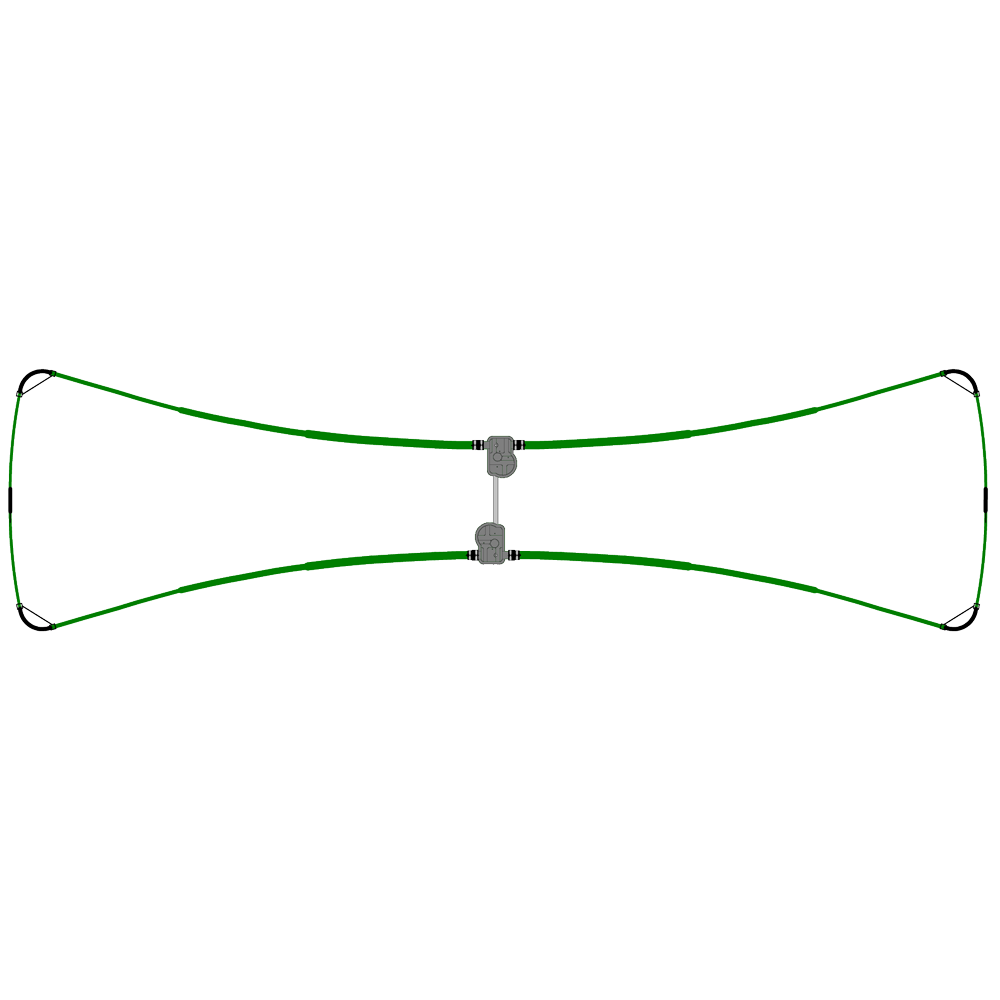
The SteppIR UrbanBeam Yagi is a fantastic choice for those that are limited by lot size, regulations (HOA’s) or even the critical eye of neighbors and spouses. The UrbanBeam has a unique appearance -some customers have remarked it looks like a bow-tie, or a butterfly! Regardless of its shape, the UrbanBeam delivers outstanding performance for an antenna that weighs only 45 lb (20.5 kg) and has a wind load of a mere 4.4 sq ft (.41 sq m). The overall physical length of the Yagi is 30.5 ft (9.3 m), which allows for a turning radius of just 15 feet (4.72 m).
The Urban Beam covers 8 ham bands (40m, 30m, 20m, 17m, 15m, 12m, 10m, 6m) and every frequency in between. On the 40m and 30m bands, the UrbanBeam functions as a dipole (continuous coverage 6.8-13.2 mHz) and takes advantage of the patented SteppIR folded loop element design, which allows for an element to be 40% shorter in overall physical length while giving up just 0.3dB of gain performance when compared to a full-length dipole. Instead of a dipole physical length of 65 feet (19.8m), the physical length is 30.5 feet (9.3 m). When the antenna is functioning as a dipole on 40m and 30m, the passive element is retracted so that there is zero potential for interaction between the two elements.
On 20m-6m (13.3-54 mHz), the UrbanBeam functions as a two element Yagi. It has a very short boom width of 48” (1.22m). There is a reason for this – the UrbanBeam draws on the Laws of Physics – when placing a parasitic element very close to a driven element, approximately .1 wavelength or less, the Yagi will achieve gain performance that is quite high for a 2 element Yagi and is more like the performance you would expect from a 3 element Yagi. There is a caveat to this, the bandwidth is greatly limited, by approximately 120 kHz. This would be a highly impractical design for a traditional fixed length aluminum Yagi, which are single-frequency devices – the bandwidth of a fixed length Yagi is very narrow unless methods such as traps or interlacing are introduced to “trick” the radio into thinking it is resonant. To put that into a simple visualization, each time you would tune the radio when using a fixed length Yagi, to achieve the same performance as the UrbanBeam (or any SteppIR antenna), a portion of each element would have to be physically removed or added – and at nearly every frequency!
SteppIR antennas adjust to the exact length required for any given frequency within their range. In other words, the signal is NOT degrading – the characteristics of the antenna change as you adjust through the bands due to spacing of the elements. When the UrbanBeam Yagi is on 20m, there are two nicely spaced elements and there is gain of 6.5 dBi free space, and front-to-rear ratio of 12dB. As the antenna is tuned towards 10m, the characteristics of the Yagi change – but in the case of the UrbanBeam, not by much. Gain and front-to-rear improve slightly – on 10m, gain is 6.65 dBi and front-to-rear is 14.8 dB.
To the experienced antenna enthusiast, this should make no sense – if element spacing gets wider, normally the gain would go up and the front-to-rear would go down – why does this not happen with the UrbanBeam?
For the Urban Beam, the spacing at the boom is 48” (1.22 m), and at the ends of the antenna the spacing is close to 9 feet (2.74 m). As the UrbanBeam is tuned from 20m-6m, because of the tapering width of the elements relative to the boom, the element spacing is gradually changing as well – which allows for very uniform performance in both gain and front-to-rear.
At SteppIR we measure our gain figures in dBi free space, it is the most realistic and objective performance evaluation for an antenna. Many of our competitors use dBd over ground for their specifications, which is fine except that the height over ground can be manipulated to make the gain figures look better than they really are. For the same reason, we use Front-to-Rear measurements for our Yagi instead of front-to-back, because when measuring front-to-back, the “back” ratio of the antenna model can be theoretically anywhere behind the front, meaning the very best performance scenario can be taken even if it is not practical in actual performance. With front-to-rear, we are choosing the exact scenario every time – directly 180 degrees behind the front lobe of the antenna.
The UrbanBeam Yagi is powered using stepper motors, located in an element housing unit (EHU), which in-turn is connected to an electronic controller via control cable. The controller is the brains of the operation, the antenna models reside in the controller firmware and it in commands each EHU to adjust to the exact length on any given frequency.
There are two controller types, the standard SDA 100 electronic controller which is included in the purchase price, or the optional SDA 2000 OptimizIR. Each will be explained in more detail later but the common features are:
180 Degree Mode: The 180 mode allows users to electrically “rotate” the antenna 180 degrees opposite the forward direction beam heading. This is accomplished with the simple press of a button, and in seconds, the transformation is complete – the Yagi is pointing in the exact opposite direction.
Bi-Directional Mode: The Bi-Directional mode function operates in a similar manner to the 180 degree mode, except when enabled, the antenna operates as a hybrid Yagi, with forward gain occurring in opposite directions, simultaneously.
Element Retract: With the Element Retract Mode, the user can retract all the elements on a SteppIR antenna to the home position, and the controller will then power down automatically. Retracting elements is an extremely valuable option in the event of inclement weather such as high winds, snow or radial icing. During lightning events, a retracted antenna greatly reduces the conductive area of the antenna platform.
Calibrate: All SteppIR antennas utilize a few watts of power to “lock” the stepper motors in-place, even when the power is turned off on the controller. This helps to keep the antenna in calibration, but it is not a critical requirement – most of the time the antenna will stay in tune regardless of power being applied. On occasion, there may be a need to calibrate the antenna. This is easily accomplished with the touch of a button – the antenna will make a growling sound as each EHU is retracted, and once completed the antenna will return to the last band/frequency it was at before the calibration commenced.
The Urban Beam Yagi has 2 purchase options:
00418-ALP
00418-ALP UrbanBeam Yagi includes the basic controller as well as PN 40-1220-343 Advanced Lightning Protection (protects the driver board of the controller by having sensitive relays in front of each driver chip, in the event of a lightning or near lightning event or even a dead short, the relays trip to protect the controller. It also allows you to have advanced troubleshooting support). Note that on a dead short situation, the antenna must not be in the process of tuning, in order to be protected.
When Purchasing the SDA 100 controller there are two options that can be purchased:
PN 40-1231-301 Transceiver interface (antenna will automatically tune to the frequency indicated on the radio, cable not included);
PN 40-1240-311 Tuning relay (locks out the amplifier from transmitting when antenna is tuning);
00418-PRO
The second version of the UrbanBeam Yagi we offer is the 00418-PRO, and the key difference here is that instead of the SDA 100 Controller, the SDA 2000 OptimizIR is included. The OptimizIR is our top of the line controller, and includes as standard equipment all three of the options you would normally need to purchase with the SDA 100 (a transceiver interface, tuning relay, and advanced lightning protection). The OptimizIR also offers a larger, full-color display and enhanced GUI. The main upgrade however, is that the OptimizIR has the capability for the user to create antenna models. Using EZNEC, Auto-EZ or other antenna modeling software on your computer, you can then download them to the OptimizIR for use on any and all bands. In addition, some cool antennas (Max gain, max f/r, and wide-angle) come stock on the OptimizIR for use straight away, and are viewable on a full color “power band” so it is easy and intuitive to visually determine the gain/FR weighting on the antenna model. Lastly, we plan on introducing an option for a Power/SWR meter, and all the OptimizIR’s that are shipping now have the “hooks” in them for purchasing that option, when available.
Other UrbanBeam Yagi Antenna Options:
Lightning Protection
When considering lightning protection – the advanced lightning protection module will provide protection for the SDA 100 or OptimizIR controller, but some people prefer to take care of lightning protection outside of the building. For that we offer the PN 20-8052-01 12-wire line protector/lightning suppressor. The lightning suppressor comes in a fully sealed weather-proof housing and protects the controller against lightning hits or near-incident lightning events. This unit often is placed just outside of the building where the operating room is located. For the best lightning protection, use both the ALP board option and the lightning suppressor.
Interface Cabling Options
With either the SDA 100 or the OptimizIR, when using the transceiver interface, a cable is required to connect from the radio to the SteppIR controller. When ordering the cable, a drop down box will appear so that you can select your specific cable for your radio. If the comm port in the back of the radio is being utilized we offer a PN 20-6014-01 Y cable, which allows the user to utilize the comm port for more than one function – our controller is querying the radio at all times, in other words listening to the radio for commands, which makes it possible to use the comm port for more than one activity .
Control Cable
The UrbanBeam Yagi utilizes PN 21-5002-01 12 wire shielded control cable (purchased by the foot) used to remotely tune the antenna, routed from the operating room to the antenna. Each active element on any SteppIR antenna employs a 4-wire shielded control cable (included) – in the case of the 2 Element Yagi, that would be 8 wires, four wires per EHU. The control cable from the EHU’s connect to one side of a terminal strip header, and the 12-wire control cable is connected to the other side of the terminal strip. Why does one side have 8 wires and the other has 12? The answer has a lot to do with supply and cost. 12 wire shielded control cable is a third the cost of 8 wire and is MUCH more readily available. When the connections have been made on both sides of the terminal strip, the bulk wiring is then placed in a plastic cylinder, and the cylinder is then attached to the boom of the Yagi.
Junction Box
The PN 70-2034 Connector Junction Box option is a bit more elegant, and much less complicated to use than the standard plastic cylinder – the necessary components are mounted inside a hinged, weather proof case, for easy access. The connector junction box has a db25 female connector mounted inside the box for connecting the controller – this way the antenna can easily be tested at the install site-point without requiring someone in the ham shack to operate the controller. Once installation is completed, the connector junction box is readily accessible for any future testing or troubleshooting.
Solder-less cable connector
When connecting the control cable to the electronic controller, there are three options – a 25 pin connector with backshell is provided, and then the control cable must be soldered (by the customer) to the dsub connector. We recommend using the PN 70-6010-01 25 pin DSub splice splice (most customers purchase this option). It is inexpensive and easy to install – simply push the bare wire ends from the control cable into the respective terminal header slot and tighten with a small screwdriver. The last option would be to purchase the “install connector at factory” option, which while convenient, is not inexpensive and can also lengthen lead times since we do not do this very often. The reason most folks don’t go this route, is because when routing the control cable from the ham-shack to the antenna, usually the routing path won’t allow for a bulky connector being on one end of the control cable.
Remote Driver Board
PN 01324 Remote driver board; The remote driver board allows the user to run control cable from the antenna to the bottom of the tower, and then run cat 5 cable up to 900 feet away. It is designed specifically for towers that are long distances from the operating location. In the event this option is purchased, the advanced lightning module is included as part of the module, which is then mounted at or near the base of the tower – the controller inside the shack has no sensitive electronics in it. Note that when ordering the remote driver board option, the user will be required to purchase a housing for it, if desired. Many people mount the bare board (it comes with an aluminum mounting plate) inside a building.
-
Weight 45 lb / 20.5 kg g *Projected Area 6.44 sq ft / 0.60 sq m Turning Radius 15.5 ft / 4.72 m Boom Length 4.0 ft / 1.22 m Longest Element 30.5 ft / 9.3 m Boom Outside Diameter 1.75 in / 4.45 cm Power Rating 3 kW Frequency Coverage **6.95 MHz—54 MHz Cable Requirements 12 conductor 22 ga shielded -
Band dBi Gain (Freespace) dB F/R (Freespace) 40 m 1.6* 9.55(F/S) 30 m 1.77** 9.63(F/S) 20 m 6.5 12 17 m 6.6 12.6 15 m 6.6 14 12 m 6.7 15.7 10 m 6.65 14.8 6 m* 6.15 4 * A full size dipole is referenced at 2.1dBi
** Measured SWR is 2.3:1 for this model on 30m
Horizontal Antennas
Vertical Antennas
Controllers/Analyzers
Antenna Accessories
Antenna Parts
Merchandise & Memberships